Optional - TFT Display
A 240x240 color TFT replaces the 16x2 LCD with a graphical spool display showing filament color, weight bar, and tag format icons.
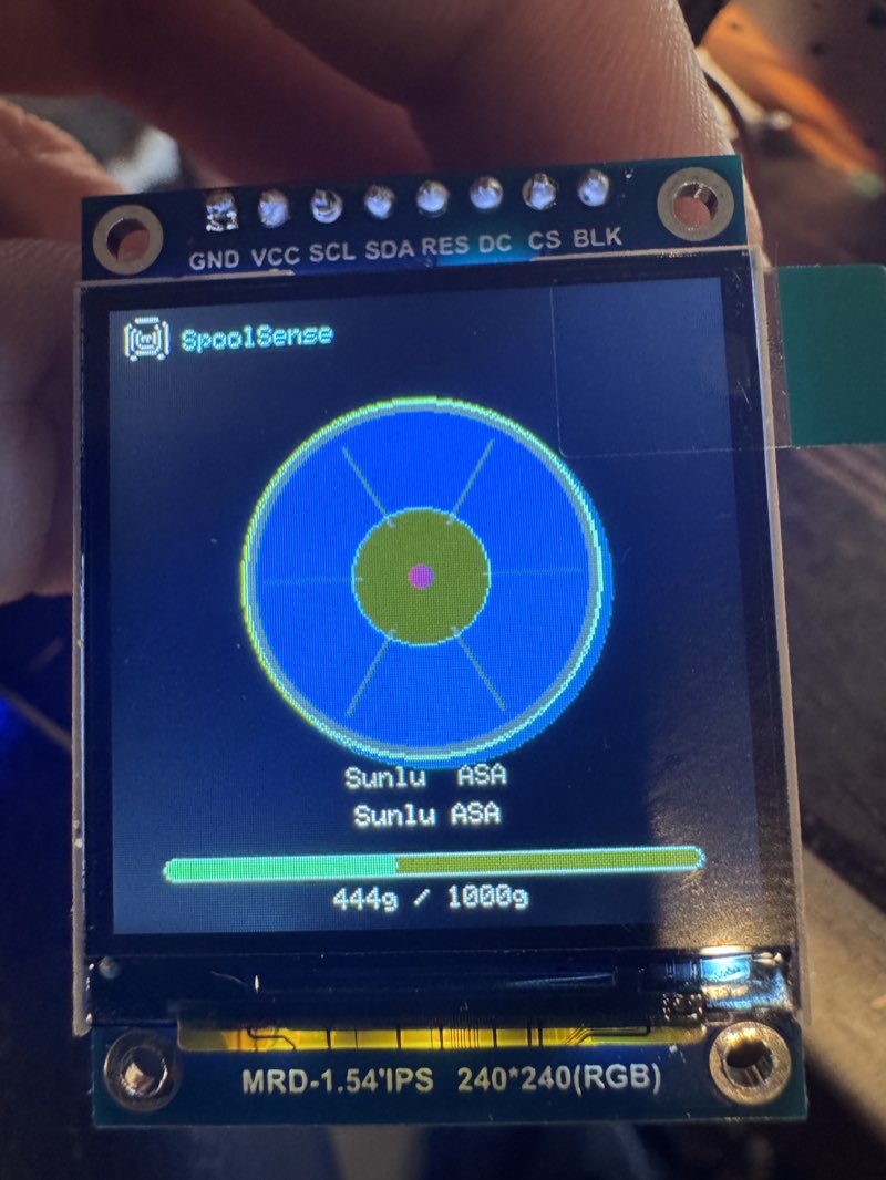
Mutually exclusive with LCD
The TFT and LCD share GPIO 22/23 on WROOM. You can enable one or the other, not both.
Not supported on ESP32-C3
The C3 variant has only one usable SPI controller, which is dedicated to the NFC reader. TFT is intentionally disabled on C3 builds.
What You Need
- 1.54" ST7789 240x240 SPI TFT module (8-pin: GND, VCC, SCL, SDA, RES, DC, CS, BLK)
- 7 jumper wires (SCL, SDA, DC, CS, RES, VCC, GND) — 8 if wiring BLK for backlight control
Wiring (ESP32-WROOM)
| TFT Pin | ESP32 Pin | Notes |
|---|---|---|
| GND | GND | |
| VCC | 3.3V | |
| SCL | GPIO 22 | SPI clock (shared with LCD SCL when LCD enabled) |
| SDA | GPIO 23 | SPI data / MOSI (shared with LCD SDA when LCD enabled) |
| RES | EN | Wired to ESP32 reset pin for reliable cold boot |
| DC | GPIO 4 | Data/command select (freed from LED when using TFT) |
| CS | GPIO 2 | Chip select |
| BLK | 3.3V | Backlight always on (or leave unconnected) |
RES pin
Wire the TFT's RES pin to the ESP32's EN pin. This ensures the display resets on every power cycle. Without this, the display may stay blank on cold boot (software reboot works fine either way).
LED pin
GPIO 4 is normally used for the status LED. When using the TFT, the LED is not needed since the display shows filament color directly. Disconnect the LED and use GPIO 4 for the TFT DC pin.
Wiring (ESP32-S3-Zero + PN532)
PN532 only
On the S3-Zero, the TFT is only compatible with the PN532 NFC reader. The PN5180 uses too many of the limited header pins (GPIO 4-12), leaving insufficient free GPIOs for the TFT. The S3-Zero has GPIO 1-13 on side headers — GPIO 14+ are back pads that require soldering.
| TFT Pin | ESP32-S3 Pin | Notes |
|---|---|---|
| GND | GND | |
| VCC | 3.3V | |
| SCL | GPIO 12 | SPI clock |
| SDA | GPIO 13 | SPI data / MOSI |
| RES | GPIO 9 | Hardware reset (freed from PN5180 BUSY) |
| DC | GPIO 3 | Data/command select |
| CS | GPIO 10 | Chip select (freed from PN5180 GPIO) |
| BLK | 3.3V | Backlight always on |
No external LED needed
The S3-Zero has an onboard WS2812 LED on GPIO 21 that still works alongside the TFT. The TFT also shows filament color directly.
Wiring (ESP32-S3-DevKitC)
The S3-DevKitC runs the TFT on SPI3, completely separate from the PN5180 on SPI2. No bus contention — both can be PN5180 + TFT simultaneously.
| TFT Pin | ESP32-S3 Pin | Notes |
|---|---|---|
| GND | GND | |
| VCC | 3.3V | |
| SCL | GPIO 13 | SPI3 clock |
| SDA | GPIO 14 | SPI3 data / MOSI |
| RES | RST | Wired to ESP32-S3 reset pin for reliable cold boot |
| DC | GPIO 16 | Data/command select |
| CS | GPIO 15 | Chip select |
| BLK | 3.3V | Backlight always on |
RES pin
Wire the TFT's RES pin to the S3-DevKitC's RST pin. This ensures the display resets on every power cycle. Without this, the display may stay blank on cold boot (software reboot works fine either way).
Best board for TFT + PN5180
The S3-DevKitC is the only board with dedicated SPI buses for both the NFC reader and TFT display. No pin sharing, no compromises.
Wiring (ESP32-C6 — shared SPI, v1.9.0+)
The C6 runs the TFT and the NFC reader on its single SPI bus. SCK and MOSI are shared wires reaching both devices; each device keeps its own chip select.
| TFT Pin | ESP32-C6 GPIO | Note |
|---|---|---|
| SCL/SCK | GPIO 6 | Shared with the NFC reader's SCK |
| SDA/MOSI | GPIO 7 | Shared with the NFC reader's MOSI |
| CS | GPIO 3 | 10kΩ pull-up to 3V3 required |
| DC | GPIO 11 | |
| RST | GPIO 18 | |
| BL | 3V3 | Backlight always on |
| VCC | 3V3 | |
| GND | GND |
Use a write-only TFT: leave the TFT's MISO/SDO pin disconnected — the bus's MISO line belongs to the NFC reader. Fit 10kΩ pull-ups on both chip selects (TFT GPIO 3 and NFC GPIO 10) so neither device is selected while the board resets.
On the ESP32-C5 the same shared-bus design is built into the firmware (TFT CS GPIO 4, DC GPIO 5, RST GPIO 23) but has not been hardware-validated yet — treat TFT on the C5 as experimental.
What It Shows
- Boot: SpoolSense logo + firmware version
- Ready: Grey spool graphic with "Tap a spool to scan"
- Spool scanned: Color spool graphic with filament color fill, weight bar, brand and material name, tag format icon
- Low spool: Breathing/pulsing brightness when remaining weight is below 100g
- Keypad entry: Large tool number with confirm/cancel prompt
- Write result: Green checkmark or red X
- WiFi/status: Connection status during boot
- AP mode: Setup instructions with IP address
Enable in Firmware
The TFT is enabled via the web config page (/config > Hardware > TFT Display toggle). No recompile needed.
Make sure the LCD toggle is off when enabling TFT on WROOM.
Compatible Displays
| Display | Size | Resolution | Driver | Status |
|---|---|---|---|---|
| 1.54" ST7789 Square | 1.54" | 240x240 | ST7789 | Tested |
| 1.3" ST7789 Square | 1.3" | 240x240 | ST7789 | Should work (same driver) |
| GC9A01 Round | 1.28" | 240x240 | GC9A01 | Supported — select in config page |
| ILI9341 panel | 2.4"–3.2" | up to 320x240 | ILI9341 | Supported — select in config page (v1.8.3+) |
| ILI9488 panel | 3.5" | up to 480x320 | ILI9488 | Supported — select in config page (v1.8.3+) |
The firmware uses LovyanGFX which supports many SPI display drivers. Any 240x240 SPI TFT with a supported driver should work with a config change. If you try a display not listed here, let us know in Discord.
GC9A01 Round Display
The GC9A01 round TFT is supported as of v1.6.10. Select "GC9A01 round" in the TFT driver dropdown on the config page (/config > Hardware > TFT Driver). Same resolution and SPI wiring as the ST7789 — same pins, just a different driver selected at runtime.
ILI9341 and ILI9488 panels
The ILI9341 and ILI9488 driver panels are supported alongside the ST7789 and GC9A01 (v1.8.3+). Pick the matching driver from the TFT Driver dropdown on the config page (/config > Hardware > TFT Driver) — no recompile needed. As of v1.9.0 the 3.5" ILI9488 gets a dedicated full-screen landscape dashboard: a 3D spool rendered in the scanned filament's colour, larger typography, and a live WiFi / Home Assistant / printer status bar. On the ILI9341 the 240x240 dashboard renders centered.
SPI Bus Note
- ESP32-WROOM: The TFT uses VSPI and the PN5180 uses HSPI — separate buses, no contention.
- ESP32-S3-DevKitC: The TFT uses SPI3 and the PN5180 uses SPI2 (FSPI) — fully dedicated buses.
- ESP32-S3-Zero: The TFT shares SPI pins with the PN5180, so TFT is only compatible with the PN532 reader on this board.
- ESP32-C6: One shared SPI bus for TFT + either reader (PN5180 or PN532) — supported in v1.9.0+ with the pull-up wiring above.
- ESP32-C5: Same shared-bus firmware as the C6; awaiting hardware validation.